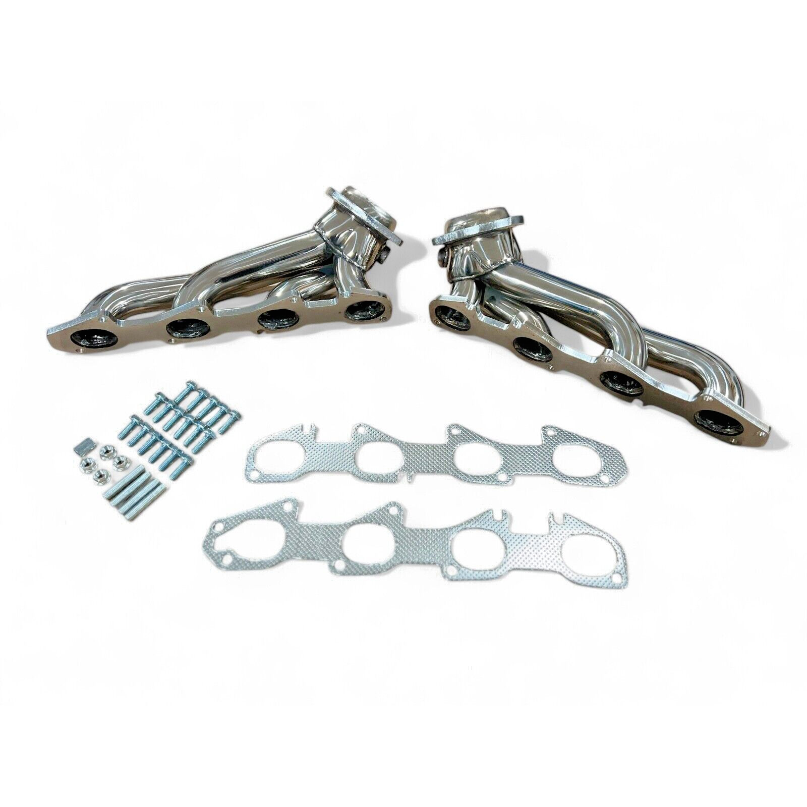
Exhaust Headers For 09-23 DODGE Challenger Charger 300 5.7L V8 304SS RT 1 3/4"
09-23 DODGE Challenger Charger 300 5.7L V8 304SS RT 1 3/4"용 배기 헤더
| 상품번호 | 356371801560 |
| 상태 | New |
| 거래유형 | 즉시구매 |
| 출고국 | 미국 (US) |
이베이 판매가
$374
약 519,486원
구매대행 예상 비용은 로그인 후 확인하실 수 있습니다.
상품 설명
2009-2023 DODGE CHRYSLER Challenger/Charger/300
Shorty Style Headers 5.7L 345Cu V8 304SS
FEATURES:
- Constructed of lightweight 1-3/4” diameter, 18-gauge, mandrel bent 304 stainless steel primary tubes maximizing strength and durability
- 3" Merged collectors for max flow and increased exhaust velocity
- 3/8” thick precision water jet cut flanges for less warping, maximum sealing surface, and better seal
- 100% hand welded construction
- Hand blended welds at the flange entry for maximum flow and better performance
PRE-INSTALLATION:
NOTE: Presoak the studs to the y-pipe and Manifold Bolts with Spray Lube or equivalent prior to starting installation.
1. Place vehicle on flat solid surface set parking brake and block front wheels.
2. Disconnect the negative terminal of the battery. Lift the vehicle a minimum of 24 inches and support with jack stands.
3. Remove both front wheels (NOT NECESSARY, BUT HELPFUL).
4. Remove the (x4) bolts securing the engine service cover under car.
5.7L EXHAUST MANIFOLD REMOVAL:
1. Unplug the (x2) O2 sensors and (x2) post O2 sensors.
2. Loosen the 15mm nuts at the clamp on the X-pipe inlet to allow the pipes to be removed.
3. Remove the y-pipe from the manifolds and exhaust system.
4. Remove the (x4) 10mm nuts (1 at each corner of each manifold) that attach the heat shield.
5. Remove the alternator support bracket (passenger’s side).
6. Remove the dipstick tube.
7. Remove the starter.
8. Remove the knock sensors.
9. Remove the engine mount heat shields from the left and right side.
10. Remove the bolt securing the steering shaft to the steering rack. Remove the steering shaft from the steering rack.
NOTE: Loop the driver’s side seatbelt through the steering wheel and latch the seatbelt. This will prevent the steering wheel from being turned while the column is disconnected and damaging the clock spring.
11. Support the engine with a screw jack or floor jack. Only lift the engine slightly to take the weight off the engine mount and hardware. NOTE: Do not support the engine from the oil pan.
12. Remove the Driver’s side engine mount pedestal assembly from the block and rubber mount from the frame rail. ATTENTION! Be very careful to keep the engine supported while the engine mounts are removed from the engine and during installation process. Failure to do so may result in severe personal injury.
13. Remove the left manifold heat shield.
14. Remove the (x8) bolts securing the left exhaust manifold to the cylinder head. Remove the exhaust manifold and gasket. Clean any debris from the cylinder head surface in preparation for the new gasket (gaskets not supplied).
15. Loosen the 2 bolts securing the right engine mount pedestal. Remove the right engine mount pedestal from the block.
16. Use the ratcheting tie down to pull the engine over to the driver’s side as far as it will go.
NOTE: Be very careful to keep the engine supported while the engine mounts are removed from the engine and during the installation process. Failure to do so may result in severe personal injury.
NOTE: 2011-12 vehicles with the old style engine mounts that have long studs through the frame rail do not require the engine to be pulled over to remove the right side engine mount bolts.
17. Remove the right engine mount.
18. Remove the (x4) bolts from the right engine mount pedestal. Remove the right engine mount pedestal from the block.
19. Remove the right manifold heat shield.
20. Remove the (x9) bolts securing the exhaust manifold to the cylinder head. Remove the exhaust manifold and gasket. Clean any debris from the cylinder head surface in preparation for the new gasket (gaskets not supplied). NOTE: Do not release the ratchet strap at this time, if used.
INSTALLATION OF HEADERS:
1. Clean the exhaust port sealing surface to remove any dirt or gasket material that may affect the sealing performance of the gasket and cause leaks. Repair any damaged threads or broken bolts.
2. Install the Right purchased exhaust manifold gasket with the supplied 8mm x 1.25 flange bolts on the bottom 4 holes. Install bolts just a few threads.
3. Hang the RIGHT header assembly on to the bolts and install the four remaining top bolts. Access to most of the header bolts can be done with the 24” extension and a 13mm swivel socket through the primary tubes (see Figure 1).
4. Use a 13 mm box wrench to tighten the bottom two bolts closest to the starter. Tighten the bolts evenly in steps from the center out until all the bolts are tight. Repeat this process several times. For vehicles mounting the dipstick tube to the manifold bolt, reuse the O.E.M studded bolt and the supplied spacer to mount the dipstick in the factory location (See Figure 2).
5. Reinstall the right engine mount pedestal on to the block. Install the engine mount into the frame and install the (x2) long bolts that will secure the engine mount to the pedestal. Release the ratchetting tie down and allow the engine to return to its normal position. NOTE: Be very careful to keep the engine supported while the engine mounts are being installed.
6. Install the Left purchased exhaust manifold gasket with the supplied 8mm x 1.25 flange bolts on the bottom 4 holes. Install bolts just a few threads.
7. Hang the LEFT header assembly on to the bolts and install the four remaining top bolts. Access to most of the header bolts can be done with the 24” extension and a 13mm swivel socket through the primary tubes and from the bottom of the header. Tighten bolts evenly in steps from the center out until all the bolts are tight. Repeat this process several times.
8. Install the left engine mount pedestal to the block and tighten the (x4) bolts. Install the left engine mount into the frame and install the long bolts into the pedestal and tighten the bolts.
9. Tighten the (x2) long bolts in the right engine mount to the pedestal. 10. Lower the engine on to the mounts and install the (x2) bolts in the left and right engine mount to the frame.
11.Install the engine mount heat shields and tighten the nuts.
12.Install the left and right pre O2 sensors in the header collectors and connect to the O2 sensor harness
13.Install the dipstick tube after checking the condition of the O-ring (replace if necessary). Vehicles with the dipstick tube mounted to the exhaust manifold bolt will re-use the factory studded bolt and the supplied spacer (Figure 2) to install the dipstick in the factory location. VERIFY THE TUBE IS IN THE ENGINE BLOCK
14.Install the alternator support bracket.
15.Install the starter and connections.
16.Install the left and right knock sensors.
17. Install the steering column on to the steering rack. Install the bolt securing the steering column to the steering rack shaft. Be sure the column is seated completely on to the shaft and the steering wheel is in the correct position. Torque the bolt to the factory recommended specification.
18. Install the left and right pipes in to the exhaust, then slide the flanges over the studs on the headers. Install the factory flange nuts and snug the flanges to the header seal ring. Align the pipes and the exhaust for best clearance at the cross brace and tighten the flange nuts. Install the secondary O2 sensors and plug in the harness. Install the starter heat shield.
19. Tighten the clamps at the header pipes and exhaust.
20. Recheck all connections and hardware to be sure all work is complete.
21. Check for proper clearance on all wiring harnesses, hoses, and lines around the headers to prevent damage from hot exhaust pipes.
22. Install the front wheels and torque the lug nuts to the factory recommended specifications.
23. Install the service cover.
24. Start the vehicle and check for leaks
25. Remove the jack stands and lower the car.
IMPORTANT! After the first 50 miles, re-check all connections and clamps. Re-torque the header collector bolts to the y-pipe